Centrifugal impact mills
Three-stage centrifugal impact mill MTZ-700 is intended for fine grinding raw materials without significant energy consumption.
Fine grinding can be carried out without internal material separation. And if such separation is provided, technical characteristics of the machine are improved. The centrifugal impact mill is capable of grinding raw materials with moisture content of no more than 4% and a melting point of more than 300 0С. The final product particle size is no more than 140 μm.
Principle of operation of the three-stage centrifugal impact mill
A loaded (using various feeders) source material is crushed by rotor blades and corresponding breaker plates. Then the crushed material under air pressure enters a machine outlet. The outlet is connected to an air duct.
Environmental compatibility of the centrifugal mill is provided by purifying a generated air mixture using a special bag filter and dust collector. A specific installation location of the centrifugal mill is selected depending on the layout of other production machines.
With the finest grinding source materials, energy consumption increases, and mill capacity decreases. This should be considered for the efficient operation of the mill.
Centrifugal impact mill MTZ-700: Technical data
| Parameters | Value |
|---|---|
| Design capacity, kg/h | 50 ÷ 700* |
| Source material particle size dн, mm | 2 ÷ 10* |
| Final product particle size dк, μm | -30 ÷-140* |
| Rotor RPM | 3,000* |
| Number of rotors | 3 pcs |
| Rotor diameter, mm | 470, 570, 670 |
| – power, kW | 37; 45; 55 |
| – RPM | 3,000 |
| Voltage, V | 380 |
| Machine weight, kg | 755 ÷ 855 |
The following auxiliary electrical equipment can be purchased additionally to your machine: power switchboards, cable products, automation systems.
Areas of application of centrifugal mills
- Processing ore: grinding ore and non-metallic materials (rock materials and ore concentrates, including wollastonite, asbestos and mica)
- Processing industrial wastes from mining and heat power facilities: slag and dump materials of heat power stations, pyrite cinders, etc.
- Fuel production: coal milling for coal-water fuel production
- Production of superhard materials: for over grinding metal, ceramic and abrasive powders for the production of functional and constructional ceramics, cermets, cutting tools, refractories and heat insulators
- Production of metal powders: for powder metallurgy and other needs – by mechanical recycling metal swarf and sheet metal
- Production of mineral pigments: grinding graphite, coke, furnace black and anti-friction materials
- Production of building materials: cements for various purposes, microcalcite (gypsum, marble, chalk), dry building mixtures, modifying additives of mortars and concrete, fillers for paints and varnishes
- Agricultural production: fertilizers, plant protection products and mixed feed
- Processing waste of various industries: joint grinding and mixing components
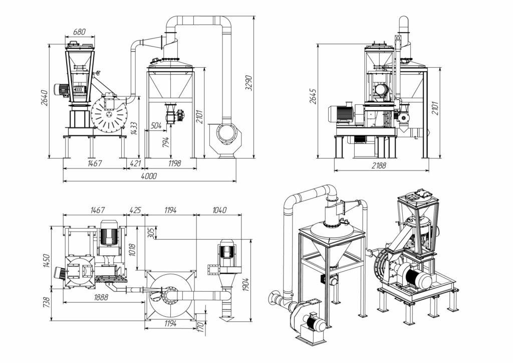
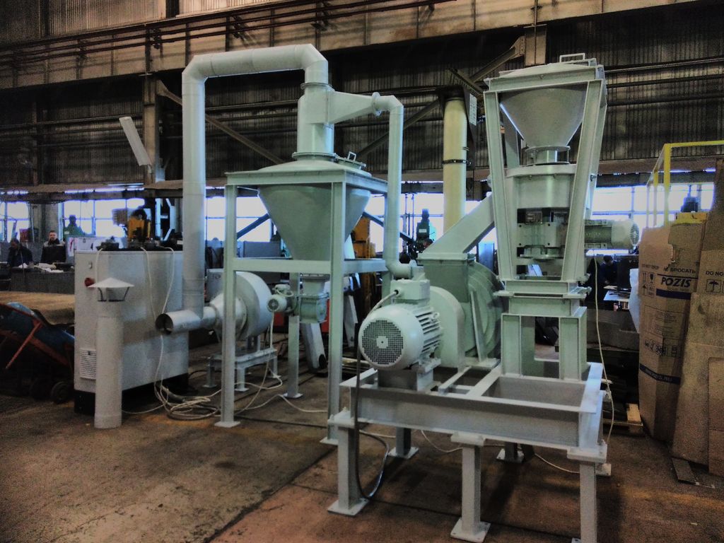
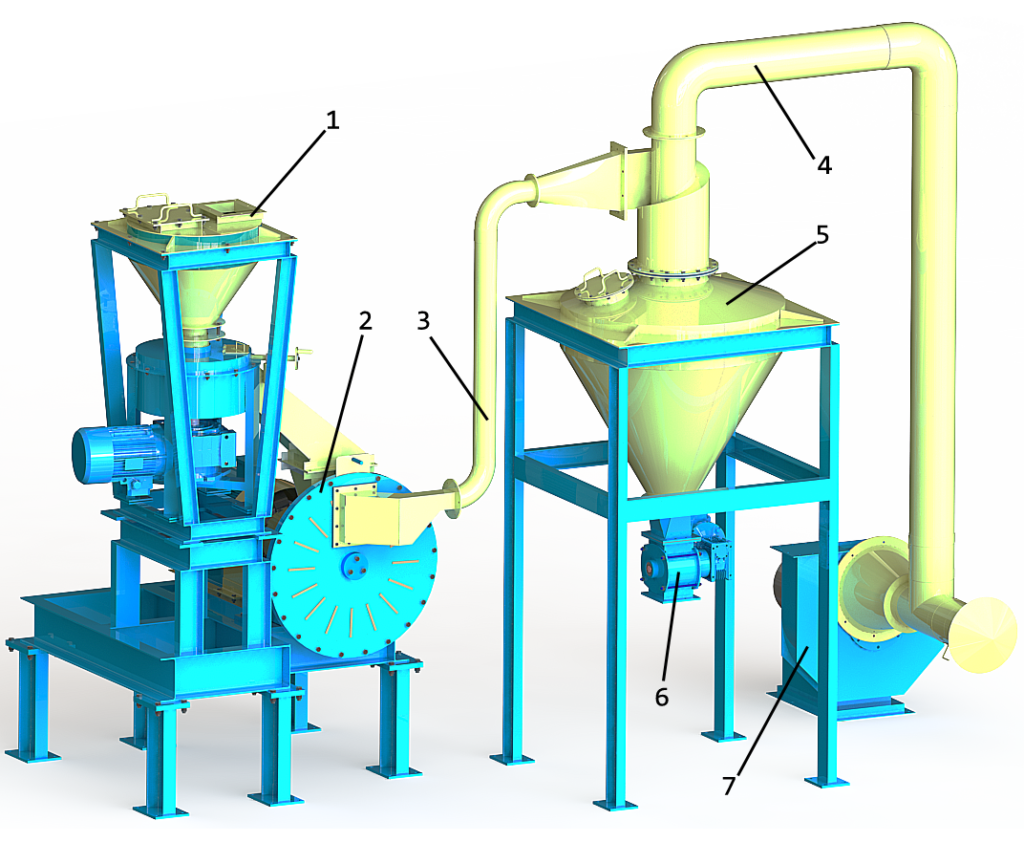
The design and principle of operation of the grinding complex based on MTZ-700
The mill includes the following equipment:
- Disk feeder: pos. 1
- Mill: pos. 2
- Air duct: pos. 3
- Air duct: pos. 4
- Cyclone hopper: pos. 5
- Sector feeder: pos. 6
- Fan: pos. 7
The complex technical data
| Parameters | Value |
|---|---|
| Design capacity, kg/h | Up to 200* |
| Source material particle size dн, mm | 100-200 |
| Final product particle size dк, μm | -45* |
| Rotor RPM | 3,000* |
| Voltage, V | 380 |
| Total power of the complex, kW | 34 |
| The complex weight, kg | 1,632 |
Disk feeder (поз.1) is a welded assembly that includes a housing, a scraper, a disk and a cover. The cover has a special door for inspections and cleaning.
The feeder works as follows: the disk rotates around its axis. The material entering the feeder from its loading hopper, under the action of centrifugal forces, moves to peripheral walls where it is continuously forwarded by the scraper (with the use of an adjusting screw) to a special output guide. Also, to control the capacity of the feeder, there is a special frequency converter with manual control. From the output guide the material enters the centrifugal impact mill.
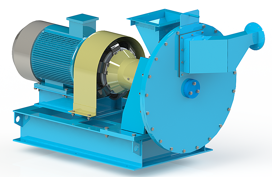
The mill (pos. 2) is a welded frame, on which there is a grinding chamber and a bearing casing with a rotor and also an electric motor. The grinding rotor is driven from the motor using a mechanical coupling. Source materials are loaded through a special inlet. The produced dust-air mixture is released through an outlet. The mixture product particle size is controlled by a special gate. The bearing casing has a cooling jacket. Outer rotating parts are guarded by a protective cover.
The source product
enters the mill through its inlet pipe. Under the action of centrifugal forces,
material particles are forwarded to the periphery of mill disks, being crushed by
rotor blades and corresponding breaker plates. The final product leaves the mill
with an air flow created by rotor blades.
It is recommended to load the mill using special feeders providing required uniform
feeding.
It is also required to connect the mill outlet to an air duct (pos. 3) of an aspiration system, in which the material is separated from the dust-air mixture.
The cyclone hopper (pos. 5) is a welded unit, which includes a cyclone-hopper and inlet and outlet ducts. There is a special door in the hopper for inspections and cleaning.
The cyclone is executed both right and left type. It works as follows: dust-air mixture enters the cyclone through its inlet. The inlet pipe is located tangentially to the cyclone casing, which upper part has a form of a helical surface providing a downward swirling dust-air flow. The separation of dust/product particles in the flow occurs under the action of centrifugal forces in the space between the cyclone casing and the outlet duct. The separated dust, by gravity, is lowered into the hopper. Unloading the hopper is carried out through a sector-type feeder (pos. 6) or other unloading device. The device works without pressure.
The sector feeder is driven by a gear motor. The material is fed into sectors of the rotor through a loading window of the housing, under its own weight. When the rotor rotates, the material moves to a housing part of the feeder and is unloaded in the lower part of the housing. The perimeter of rotor blades is lined with rubber, which allows to create the required seal between rotating parts and the housing. The purified air flows through the air duct (pos. 4) tothe fan (pos. 7).